
Thermography Service
We are engaged in providing our clients Electrical Thermography By Qualified Professionals. An infrared electrical inspection can minimize injury, liability, damage, catastrophic failures and downtime of the organization
- Many conventional electrical problems have unconventional answers, which are not revealed in routine inspection. Small faults may be negligible but could create lasting damaging effects to life & property in the long run.
- In electrical systems component's age, fatigue, oxidation, wear & tear, loose connections , poor installation can increase resistance & heat .
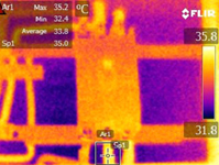
- Infrared cameras catch this heat.
- This is why an Infrared electrical inspection is the best way to detect early electrical failures, because most electrical things tend to get hot before they fail)
- Switchgear in organization and substations
- Transformers
- Power transmission lines
- Distribution panels, circuit breakers and conductors
- Computer and low voltage systems
- Machine control Panels
- PLCs (Valves & Relays)
- Infrared Thermal imaging can help you detect problems like inductive heating, hot bus bar ,overloaded circuit & many undesirable electrical situations
- It can be used to measure or observe in areas inaccessible or hazardous for other methods
- It is a non-destructive test & contact free method
- Thermography inspect electrical objects in dark areas
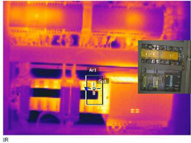
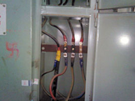
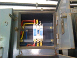
- An Infrared inspection can immediately detect an overheated wire in the mesh of wires and terminals, which is impossible to see with naked eyes.
- An infrared electrical inspection can minimize injury, liability, damage, catastrophic failures and downtime of the organization An effective preventative maintenance strategy must include an infrared scan.
Thermal imaging is an extremely useful tool for electrical fault finding. It requires no contact being made with the components which means that the components can be checked in a live state with little danger to the user, there is no effect on the components or interruption in any processes the electrical system may be controlling.
- Corroded or loose connections
- Imbalanced Loads
- Using underrated equipment or overloading equipment
- Insulation Damage
- Incorrect voltage
- Blocked or poorly ventilated equipment
- Deterioration due to age
- Exceeding the recommended temperature rating
- Motors and motor control panels
- Control equipment
- Cable runs
- Substations
- Transformers
- Circuit operating devices
- Thyristor banks
- Switches, fuses and circuit breakers
- Distribution boards
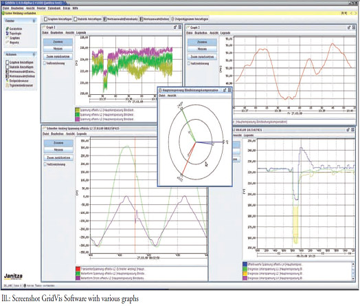
IR Inspection mainly involves scanning, image taking and image analysis and among them analysis part is most important for correct diagnosis of problems.
Failure of equipment, machine in electrical or any system may result in loss of production, injury, fire or other damages to property etc., all resulting financial loss. IR Inspection identifies fault sites in advance and suggests for corrective actions based on fault severity. IR Thermography removes unnecessary preventive maintenance and typically in ordinary circumstances 30 to 40 % of the maintenance costs can be saved.
We shall cover the following under scope of work for Thermography:

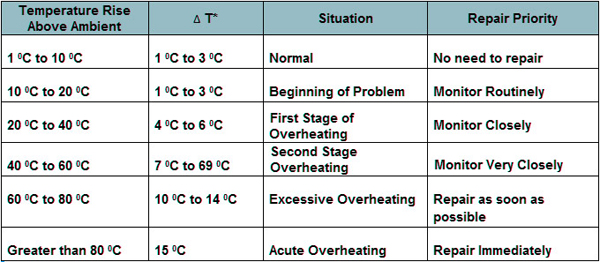
Temperature Variation reference chart-